Ind 2/R
| Instruction CMS block | Ind 2 guide |
|---|---|
| Tester | No |
Installation Guide
Industrilas Compression Handle
Industrilas handles have been used on RSI Smart Caps before 2021 & Alu-cab Canopies.
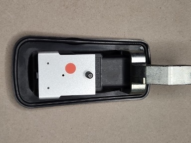
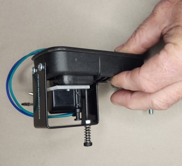
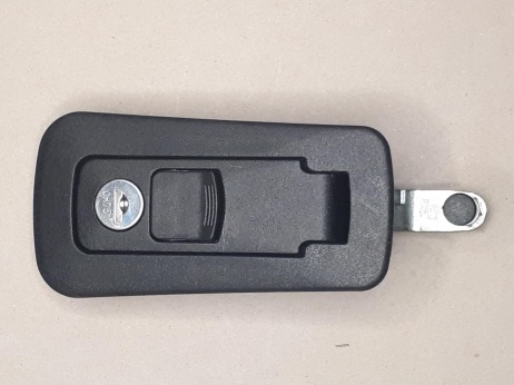
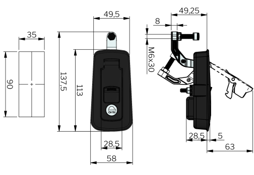
This Installation guide is for our central locking adaptors with internal release button to suit Industrilas 2-398 Polyamide (Nylon) compression handle with nylon mounting bracket the same dimensions and as shown in the below picture and pictures on page 4 of this guide, installed in 1.5mm thick material. Handle has Industrilas written on the back & on the key.
No wiring is supplied with this kit. This kit must only be installed by a competent person. No handle is supplied with this kit and the handle in this guide is shown for illustration purposes only.
Read complete installation guide before continuing.
Kit Contents
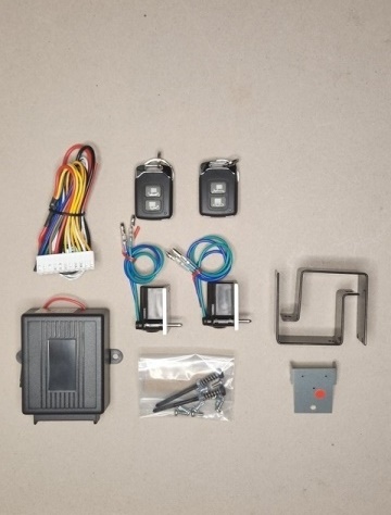
Ind 2/R
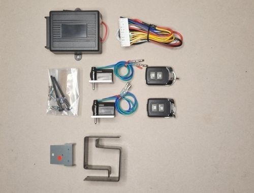
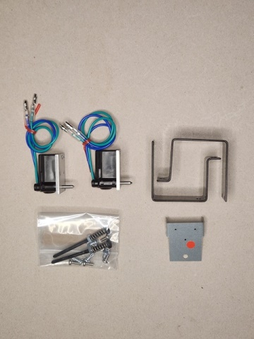
2 x Locking Actuators 1 x Drilling Template
4 x M3 x8 Screws 4 x M3 Spring Washers
2 x Optional internal Open Pins 2 x Protection Brackets
4 x 6g x 10 Self Drill Screws Remote Control
Ind 2
2 x Locking Adaptors 1 x Drilling Template
4 x M3 x 8 screws 4 x M3 spring washers
2 x Optional internal open pins 6 x protection brackets
4 x 6g x 10 self drill screws
Suggested tools
Drill press 1.5mm hss drill 3mm hss drill
3.5mm hss drill Loctite or similar PH 1 Screwdriver
1. Check your handle is of same dimensions and is the same as above picture, and in the pictures below, and there is at least 38mm behind the flat of the handle body.
- Remove handle from canopy.
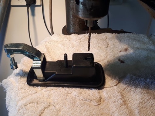
- Place template over stud and make sure the template sits flat on handle body. Picture 1
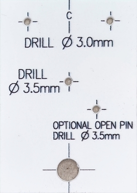
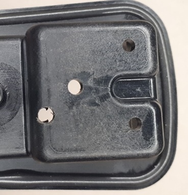
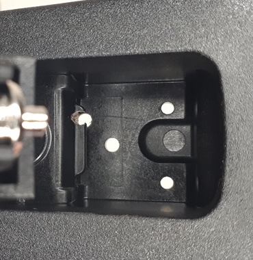
- With handle in the closed position and locked with the key (This is so the internal latch doesn`t move when drilling) hold the handle in a drill press. (I used a rag on the drill press so not to scratch the handle) Drill only 3 holes with a 1.5mm drill through the template, not the hole with the red sticker on it. Remove the template and drill 2 x 3mm & 1 x 3.5mm as shown in picture 2, Do not drill the optional open pin hole with the red sticker over it until the next step. Holes must be at 90 deg to handle body, picture 3. Drill the 3.5mm hole through handle body and locking latch, picture 4 (approx. 7mm deep from top of handle body). Ensue all burs and swarf is removed from handle.
- If installing the optional internal opening pin
- Remove the red sticker and place the template over the stud and flat on the handle body, with the handle open and supported in the drill press. Handle must be in the open position for this step. Drill through the template and the handle body at 90 degrees from handle body and through the locking bar inside the handle with a 1.5mm drill, then remove the template and drill the hole out to 3.5mm, pictures 5 & 6. Remove all burrs and swarf from inside handle.
- Reinstall the handle in canopy.
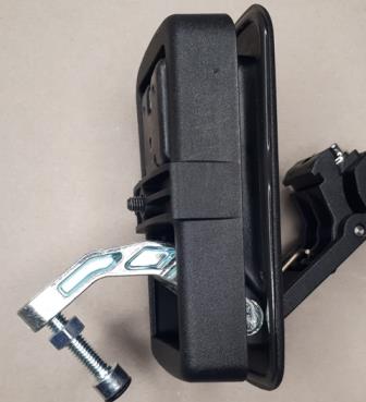
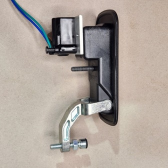
- Using the supplied M3mm x 8mm pan head screws & spring washer, install the locking actuator onto the handle, pictures 8 & 9. Check that locking pin on the actuator is locking and unlocking, this can be done with a 12-volt supply, or a 9-volt battery will work for this test, check with the handle in the open and closed position. Note: Loctite or similar can be used on the thread of the pan head screws to ensure they do not become loose from vibration.
- Remove nut from stud and install protection bracket, screw end of protection bracket to handle mounting bracket using 2 of the 6g x 10 self-drill screws supplied, picture 11. When installing the protection bracket make sure that top of bracket is parallel to handle body and the sides are even with the actuator aluminium mounting plate, this is important if installing the internal opening pin.
- Installation of optional opening pin
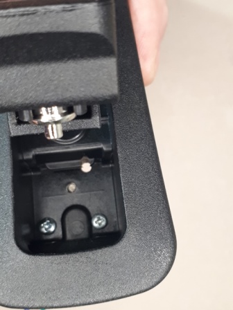
- Install the spring onto the pin and insert the pin into the top of the protection bracket, then screw the M4 nut onto the pin and put the end into the hole in the handle with the flat of the pin next to the actuator mounting plate. Screw the nut up until there is approx. 0.5mm of play. Test to make sure the pin opens the handle when pushed in and the handle stays closed when handle is closed, if handle pops open when trying to close, unscrew the nut until handle stays closed. Mark where nut is on the pin and loosen then apply Loctite or similar to the thread and screw nut back to correct position. Pin should be held into position with spring tension.
- The handle can still be locked with the key, however the internal open pin only works when both the key and the central locking actuator are in the unlocked position, and the key has to be in the unlocked position for the central locking to work.
- If you purchased a remote control from Canopy Locking Systems follow the remote control installation guide to connect locking actuators.
- If connecting the locking actuators to the vehicle central locking we recommend that an auto electrician do the connection for this. No wiring diagram is supplied for this option.
Canopy Locking systems takes no responsibility if this guide is not followed and holes are drilled in the wrong position.
A copy of this document can be found at https://www.canopylocks.com.au/alu-cab/ind-2-r.html.
Warranty is 12 months from invoice date for all parts supplied in the kit. Warranty will be void if any of the supplied parts are altered in any way, including cutting bullet connectors off actuator wires.
Specification: Actuator 12 Volts, stall current 2 x Actuators 600 mA