SCH 4
| Instruction CMS block | SCH 4 guide |
|---|---|
| Tester | No |
Installation Guide
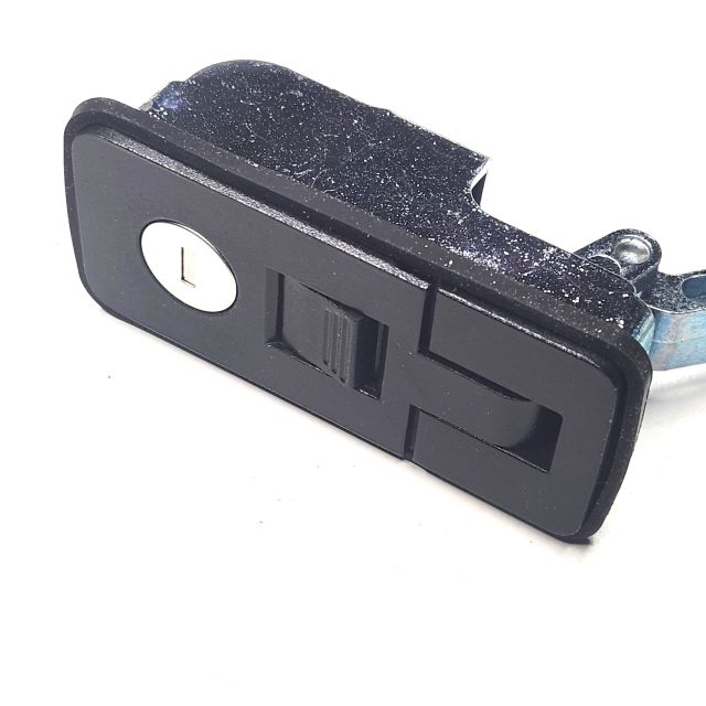
Small Compression Handle
Small compression handles are typically used on canopies, trailer doors, caravans, cabinets and many other applications.
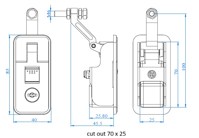
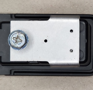
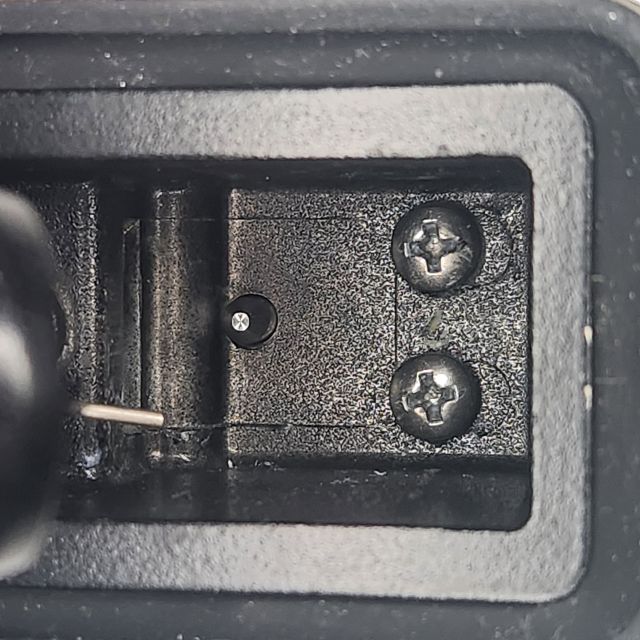
This installation guide is for our central locking adaptor kit which suit small compression handles of the same dimensions and as shown in the below picture and in the pictures on page 3 of this guide.
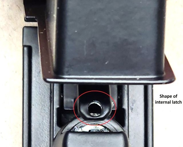
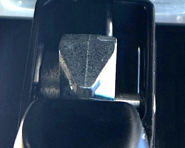
Take note the internal latch must be the same shape as shown in the types of internal latches pictures below or the adaptor will not work. If your unsure please send us a picture and we will be able to tell.
No wiring is supplied with this kit. This kit must only be installed by a competent person. No handle is supplied with this kit and the handle in this guide is shown for illustration purposes only.
Read complete installation guide before continuing.
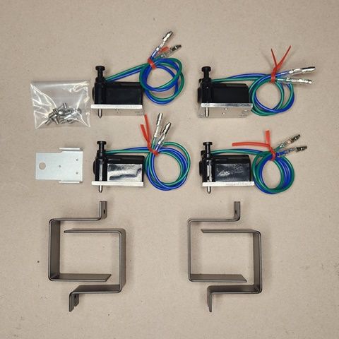
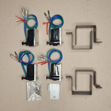
Kit Contents

Suggested tools
Drill press 1.5mm hss drill 3mm hss drill 3.5mm hss drill Loctite or similar.
PH 1 Screwdriver Countersink bit
Check your handle is of same dimensions and is the same as the above picture and the pictures on page 3 of this guide. Take note that the internal latch must be the same shape as shown in types of internal latches pictures below or the adaptor kit will not work. If you’re unsure, please send us a picture and we will be able to tell.
1. Remove the handle from the door.
2. Place the template on the handle as shown in picture 1, making sure the template is flat on handle body.
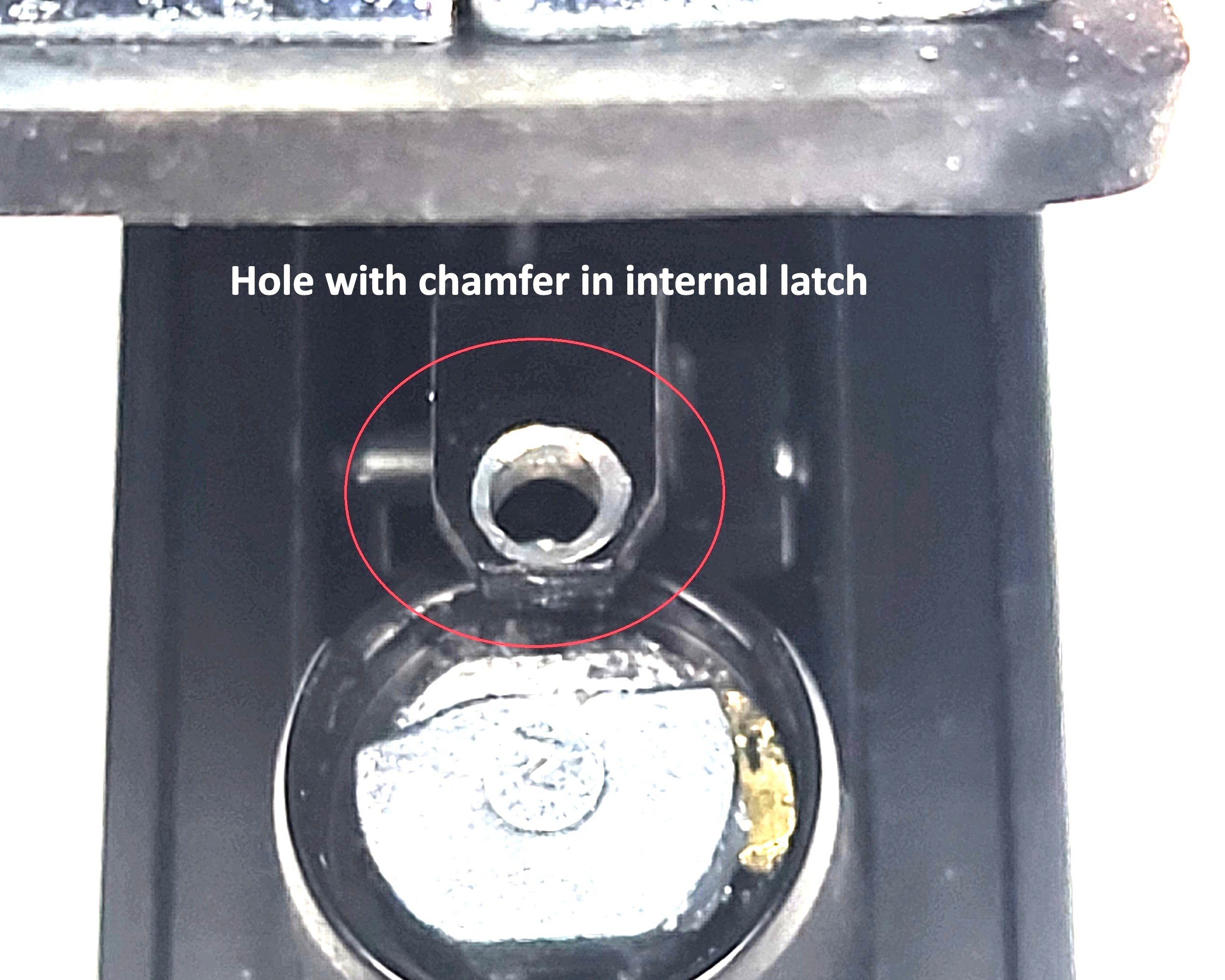
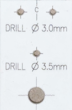
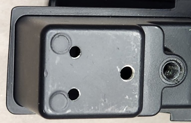
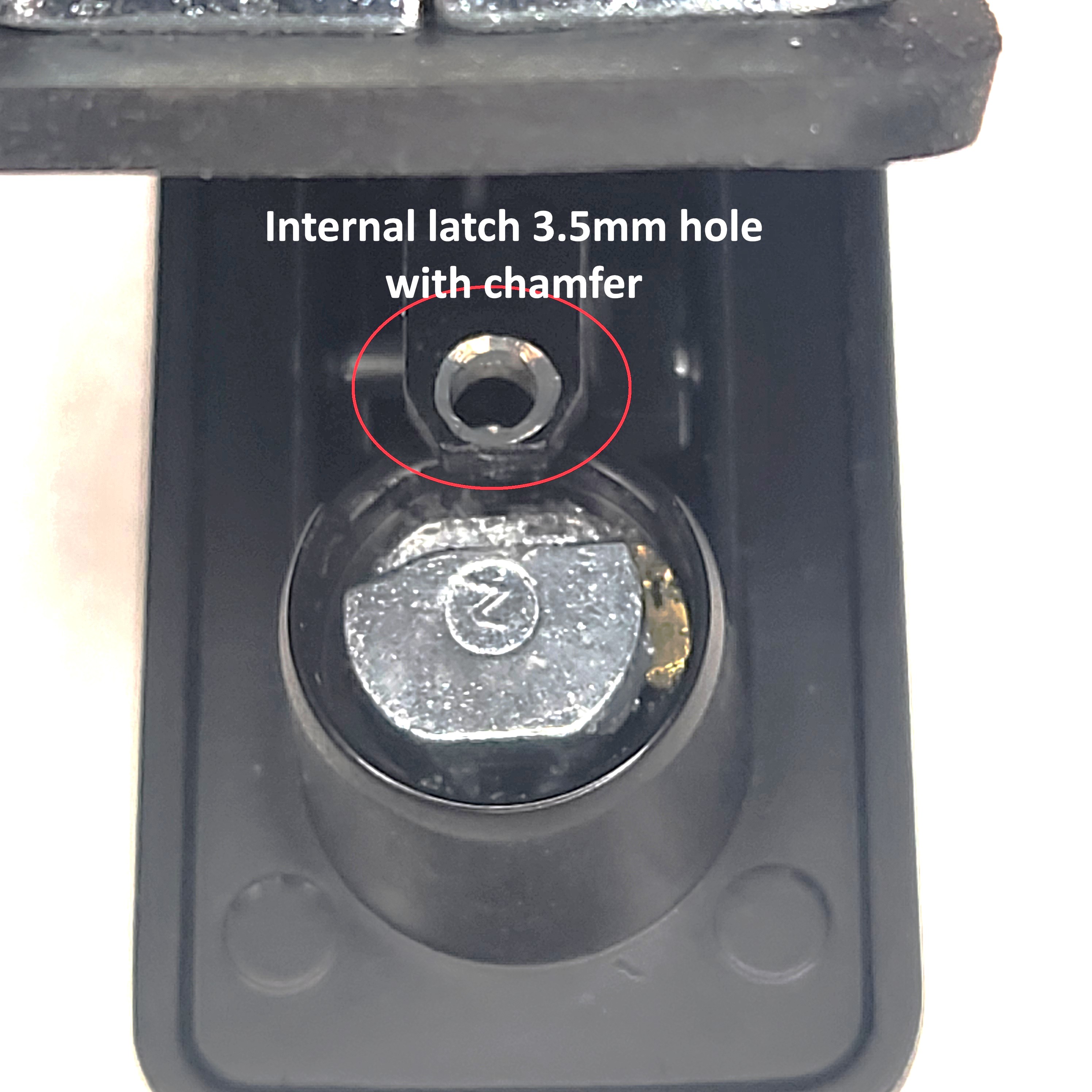
3. With handle in the closed position and locked with the key (this is so the internal latch doesn`t move when drilling) hold the handle in a drill press (I used a rag on the drill press so not to scratch the handle). Drill the 3 holes through the template and handle body with a 1.5mm drill. This is to ensure the hole centres are accurate. The centre hole must also be drilled through the internal locking latch. (approx. 111mm deep from the top of the handle body). Then remove the template and drill the 3 holes as shown in picture 2, (2 x 3mm & 1 x 3.5mm). Holes must be at 90 deg to handle body, picture 3. Drill the 3.5mm hole through handle body and the internal locking latch, (approx. 11mm deep from the top of the handle body). and add a small chamfer to top of the hole drilled in the internal latch. Picture 4. Ensure all burs and swarf is removed from inside the handle.
4. Reinstall the handle in the door, then using the supplied M3mm x 6mm pan head screws and spring washers install locking actuator onto the handle. Picture 5. It is recommended that Loctite or similar be applied to the threads of the screws that secure the locking actuator, so they don`t work loose over time. A dob of grease on the screwdriver tip helps keep the stainless-steel screws on the screwdriver. Then install the protection bracket using the mounting screw to keep it in position. Picture 6
5. Check that locking pin moves freely through the hole in the handle body, if not loosen the 2 screws and slightly move the actuator and re-tighten the screws and retest. Also make sure the locking pin is engaging with the internal locking latch by either manually pushing the actuator pin in (towards the handle body) or momentarily applying power to the actuator. A 9-volt battery will work for this test. If the pin is engaging with the internal latch the button on the handle will not press down.
6. The handle can still be locked with the key; however, the key must be in the unlocked position for the central locking to work.
7. If you purchased the SCH 4/R, follow the remote-control installation guide to connect locking actuators.
8. If connecting the locking actuators to the vehicle central locking, we recommend that an auto electrician do the connection. No wiring diagram is supplied for this option.
Canopy Locking Systems takes no responsibility if this guide is not followed, and holes are drilled in the wrong position. If unsure about any steps, please contact us at sales@canopylocks.com.au
A copy of this document can be found at
https://www.canopylocks.com.au/small-compression-handle/sch-4-r.html.
Warranty is 12 months from invoice date for all parts supplied in the kit. Contact sales@canopylocks.com.au for all warranty claims. Warranty will be void if any of the supplied parts are altered in any way.
Specification: Actuator 12 Volts, stall current 4 x Actuators 904 mA
Internal latch types
Install guide pictures

Remote control unit installation guide
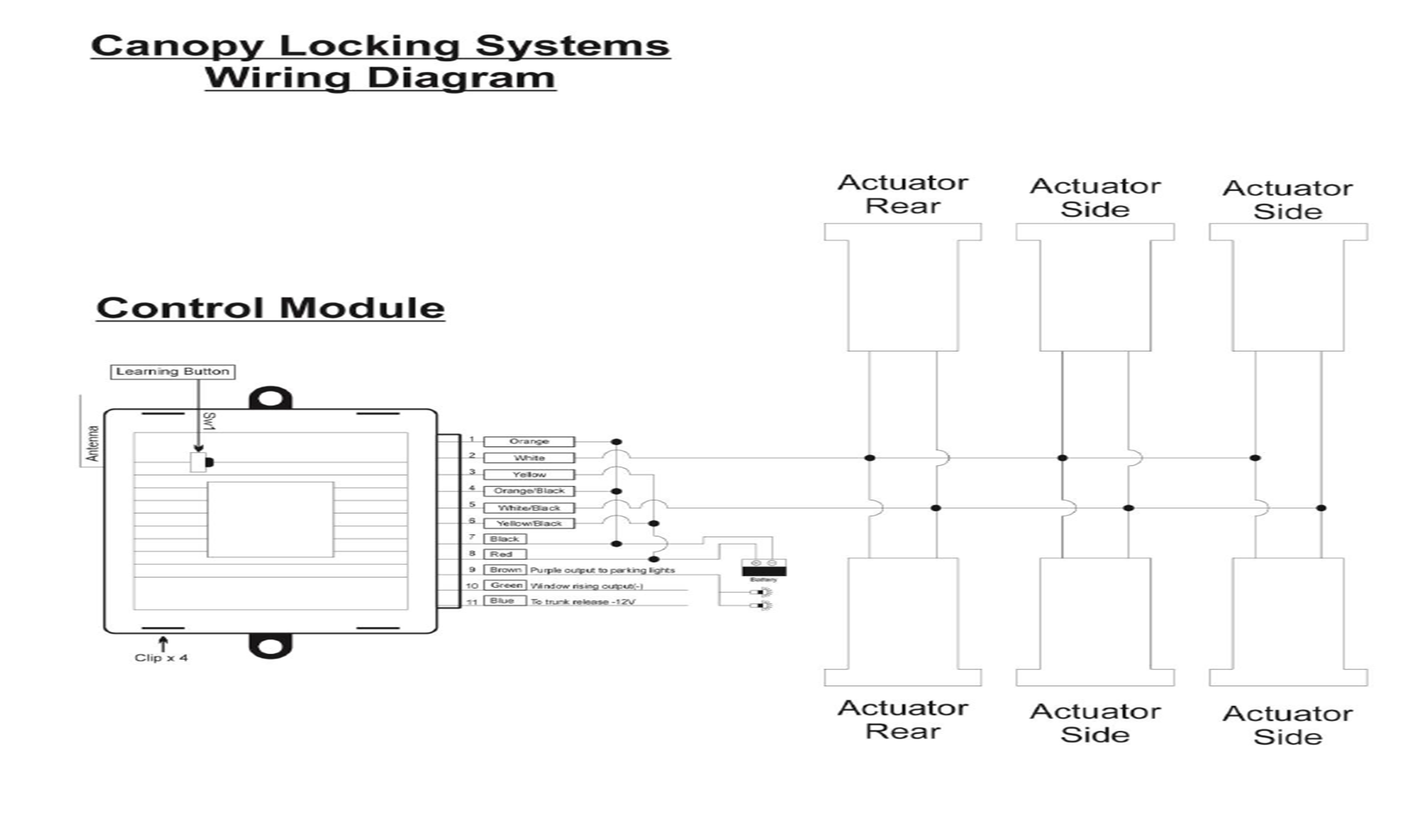
Mount controller anywhere in cabin or somewhere that is waterproof and accessible (this is important for accessibility in the event of unforeseen failure). Now referring to the wiring diagram below, run a 15-amp cable to the controller from a positive power source to the red wire. Connect the black wire to the negative. Then run 2 wires (3mm 10 amp) from the controller white & white/black to the first actuator and then loop wires to all other actuators, using loom tube and stick on mounts to secure the wiring. Connect all actuators to the cabling using female bullet connectors and the connect power to the controller.
Operate the remote controller and make sure all actuators travel in the same direction at the same time and when the lock button is pressed all are in the locked position. If any actuators are not travelling in the same direction, then reverse the connection at the actuators travelling in the wrong direction.
Pairing fobs to control unit
1 Open module by levering top of unit away from bottom at the 4 x clip points.
2 Press and hold the learn button and press any button on the fobs to be paired.
Green , blue & brown wires on control unit are not used.